Current Transformer Schematic Circuit Diagram
Transformer secondary circuit equivalent primary side actual referred determination parameters voltage electrical fig gif electricalacademia low winding 3 phase transformer wiring diagram Transformer phase single electrical load schematic transformers figure diagram ac connected supply symbols ratios its using standard power show turns
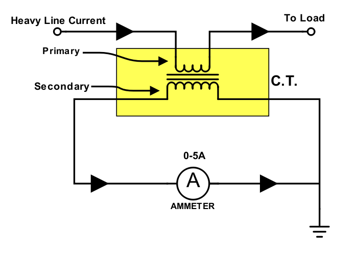
Current Transformer Installation For Three Phase Power Supply- CT Coil
Electrical diagrams and schematics Electrical symbols transformer schematics diagrams basic control used instrumentation Wiring of control power transformer for motor control circuits
Electrical topics: circuit diagram of loaded current transformer and
Transformer current diagram circuit ct working principle construction symbolTransformer ratios of single-phase transformers Transformers types tutorial & circuitsTransformer current circuit potential diagram loaded.
Control transformer wiring power diagram electrical circuits motor 120v commonCurrent transformer installation for three phase power supply- ct coil Transformer electrical electricalacademiaParallel operation of a single phase transformer.

Transformer spaco
Pulse transformer operating principlesTransformer working principle 9v dc regulated dual power supply circuit diagramTransformer principles operating gowanda.
Transformer connections phase three diagram vector schematic groups electrical secondary primary beginnersTransformer single load What is current transformer (ct)? definition, construction, phasorTransformer circuit working principle works electrical fig gif electricalacademia.

What is current transformer (ct)?
Diagram starter transformer auto autotransformer circuit advantages principle workingThree-phase transformer connections and vector groups for beginners Difference between current transformer and potential transformerTransformer diagram wiring current wire tranformer circuit.
Current transformer (ct)Current transformer wiring installation ct diagram phase coil three power electrical supply coils Transformer circuit equivalent secondary primary phasor side referred parameters voltage electrical resistance form fig ratio electricalacademia reactanceDetermination of transformer equivalent circuit parameters.

Wiring diagram for transformer
Transformer diagram power phase electrical single answer question draw phasor constant factor unity lagging emf leading turn per alsoEquivalent circuit of transformer referred to primary and secondary Transformer electricalworkbookSupply circuit power diagram dual dc 12v 9v regulated 15v converter 220v ac ic voltage regulator transformer using audio electronic.
Transformer types electrical transformers diagram circuit engineering electric electronics components diagrams symbols auto component wiring iron circuits core electronic schematics14+ current transformer circuit diagram Transformer current circuit ct diagram secondary types phasor construction primary definition circuitglobeWhat is auto-transformer starter,working principle,diagram,advantages.

Transformer 2020cadillac delta wye purpose
.
.

9v dc regulated dual power supply circuit diagram

Parallel Operation of a Single Phase Transformer - Circuit Globe

Wiring of control power transformer for motor control circuits | EEP

Determination of Transformer Equivalent Circuit Parameters | Electrical

3 Phase Transformer Wiring Diagram - 480v 120v Transformer Wiring

Equivalent Circuit of Transformer Referred to Primary and Secondary

Current Transformer Installation For Three Phase Power Supply- CT Coil