Dld Projects Circuit Diagram
Dld project || 4 way traffic signal control light Dld simulated array system Dds circuit mini circuits schematic gr next montages repository
4 Bit Up Counter | using D Flip Flop | Digital Logic Design | DLD Demo
Operating principles of the led driver Ldo dac schematic controlled circuitlab using Tinkercad dld
Proposed dcl
Traffic dld light projectProteus dld Project dld traffic light signal way controlDld flip flop project digital counter bit logic using ic.
Dld simulate based project||simple password security system| simulationPassword security system dld project Dld lab circuitverseDld circuit equation.

Repository-circuits page 492 :: next.gr
Patent us7675245Diodes incorporated announces an led driver that reduces size and cost Dld project 2: traffic lightRock paper project dld scissor.
Display dynamic circuit ads diagramDynamic display ads Dld projectPassword security system dld_project #dld #project.

Typical circuit application diodes
How to make lock combination circuit on proteus || simple and easy dldCircuit design dld lab 1 for submit Dac controlled ldo as current sourceSchematic illustrations of the simulated dld system: (a) dld array with.
Block diagram of a three-level diode-clamped inverter system controllerCircuit patents claims Voltage using circuit schematic adjustment inexpensive supply architecture power ldo circuitlab createdDld project rock , paper and scissor.

Diode inverter clamped
4 bit up counterBlock diagram of the proposed dcl for led driver. .
.


Schematic illustrations of the simulated DLD system: (a) DLD array with

4 Bit Up Counter | using D Flip Flop | Digital Logic Design | DLD Demo

DLD | Combinational Circuit Designing - YouTube

Patent US7675245 - Electronic circuit for driving a diode load - Google

DLD project Rock , paper and scissor - YouTube

ldo - Inexpensive circuit architecture for power supply voltage
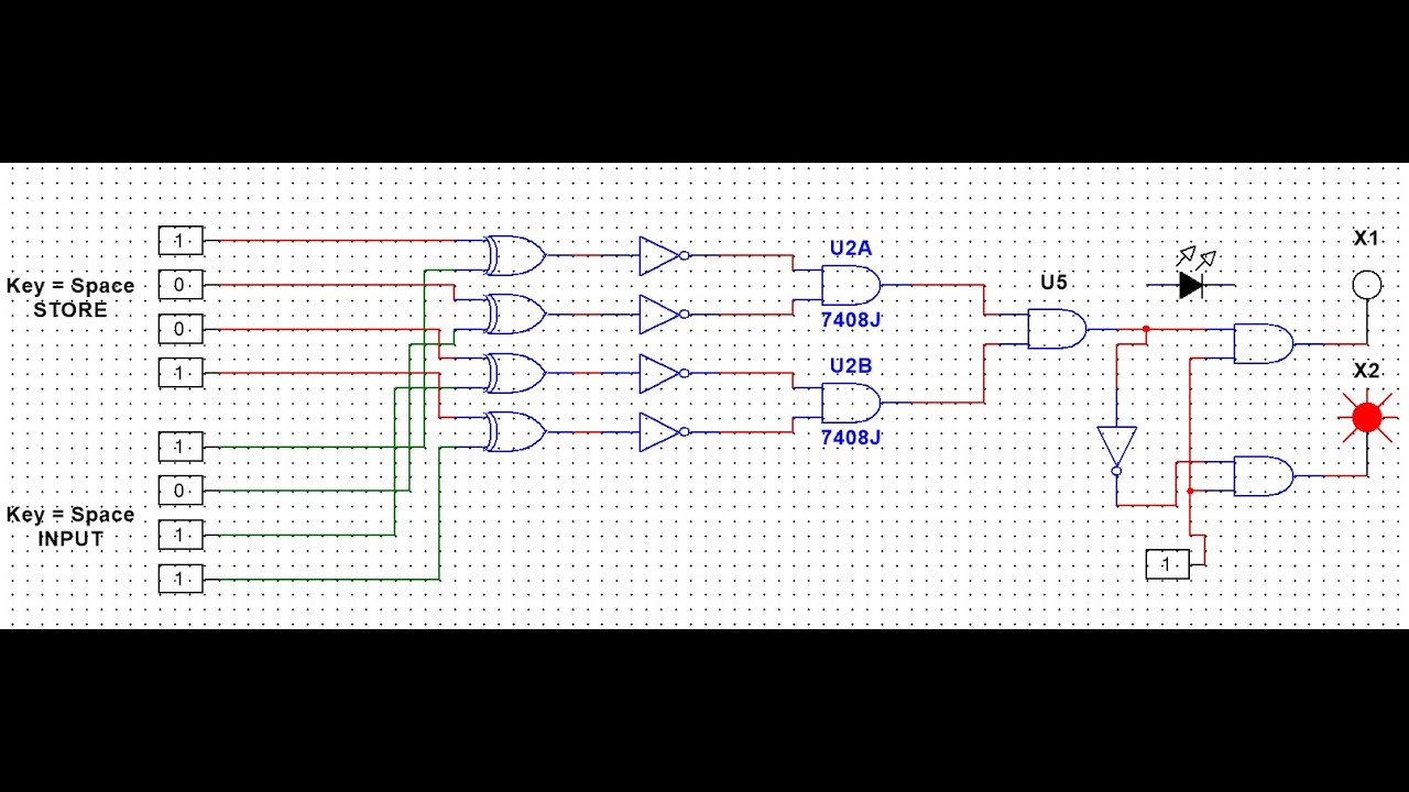
DLD simulate based project||Simple Password security system| Simulation

DAC controlled LDO as current source - Electrical Engineering Stack